UC-DE-1
Categories:
1. Description of the Use Case
1.1. Name of the Use Case
| ID | Area /Domain(s)/Zone(s) | Name of the Use Case |
|---|---|---|
| UC-DE-1 | Area: Energy systemDomain: Distribution, Customer Premise, Field, DERZones: Operation, Enterprise, Process, Field | Island ModeImplementing of an Energy Management System that operates a specific low voltage network in virtual island mode, i.e. minimizing the power exchange with the connected medium voltage feeder by utilizing available flexibility (local energy storage systems and controllable loads) |
1.2. Version Management
| Version No. | Date | Name of author(s) | Changes | Approval status |
|---|---|---|---|---|
| 0.1 | 1st June 2020 | Thorsten Gross | Initial creation | Draft |
| 0.2 | 2nd June 2020 | Katarzyna Zawadzka | Initial creation in Github | Draft |
| 0.3 | 16th June 2020 | Benjamin Petters | Extended description and added technical part | Draft |
| 0.4 | 17th June 2020 | Navreet Dult | Review | Draft |
| 0.5 | 18th June 2020 | Thorsten Gross | Review | Draft |
| 0.6 | 18th June 2020 | Benjamin Petters | Revision | Draft |
| 0.7 | 22nd June 2020 | Padraic McKeever | Revision | Draft |
| 0.8 | 29nd June 2020 | Benjamin Petters | Revision | Draft |
| 0.9 | 23rd July 2020 | Benjamin Petters | Review | Draft |
1.3. Scope and Objectives of Use Case
| Scope | A local energy community - With the new Clean Energy Package, private households are encouraged not only to generate and consume energy, to market the flexibility of controllable producers and consumers in the future, but also to make energy available to each other and to share generated energy. In the future energy distribution network, the new regulatory framework, technical developments and grid fee mechanisms canmotivate households to found and/or join energy communities with the aim to maximize the consumption of locally generated energy. Communities with a high penetration of photovoltaic systems and correspondingly large installed generation capacity can be expected to generate an energy surplus during times of peak generation and low local demand, and vice versa to run into an energy deficit during seasons of low generation. Surplus energy can be stored and shifted to times of low generation in order to satisfy temporary demand and hence increase the degree of self-sufficiency up to 100%. Networks: LV Markets: None |
| Objective(s) | - Maximize consumption of local generation/Minimize demand satisfied by public grid - Islanding of local grid by making use of flexible loads and storages - Maximizing duration of islanding operation - UC 1 is prerequisite for UC 2 to 4 |
| Related business case(s) | no |
1.4. Narrative of Use Case
Short description
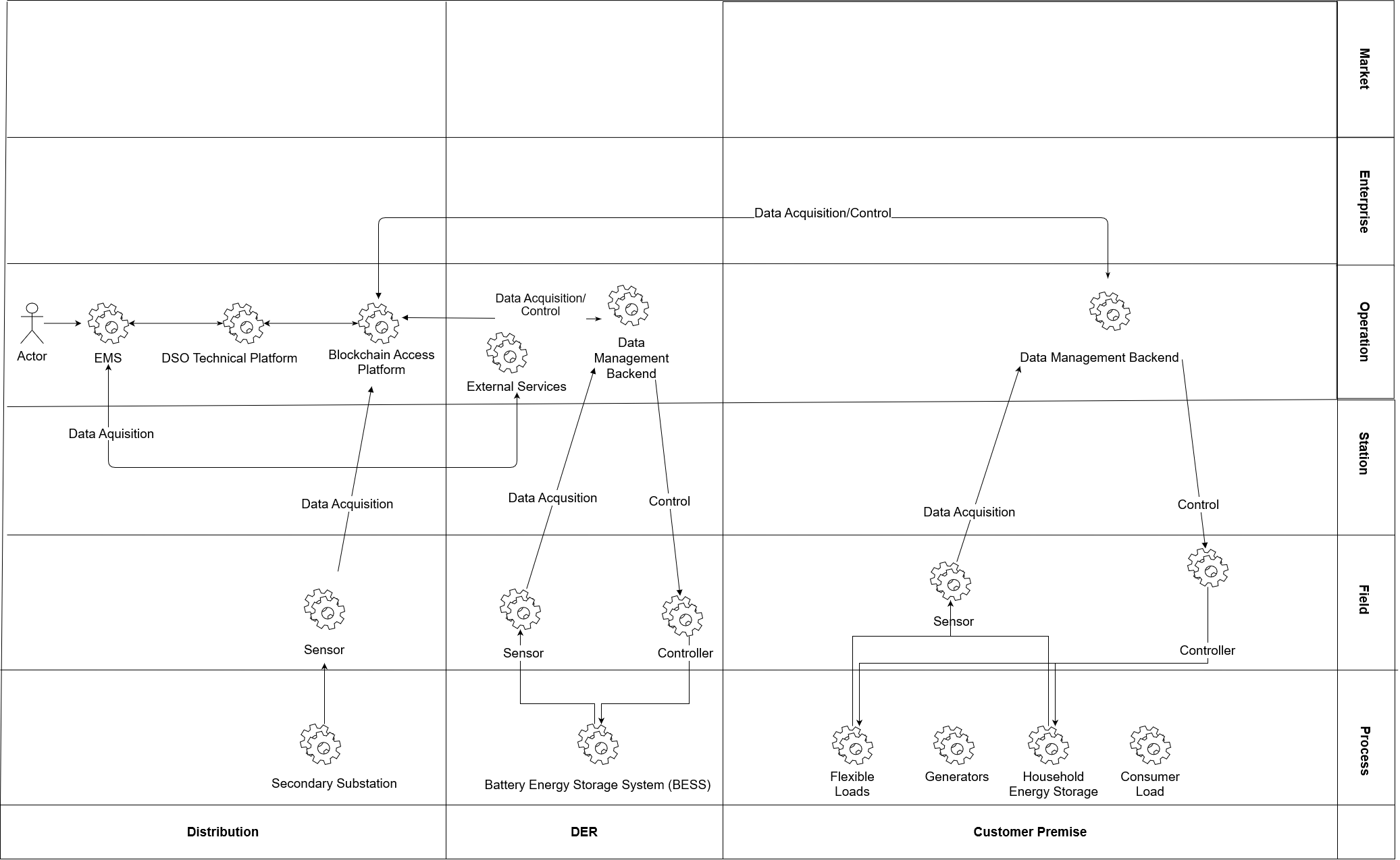
The use case “Islanding” of an energy community aims to balance generation and demand of a local energy community in such a way that the load flow across the connecting MV/LV transformer is reduced to a minimum. The balancing is enabled by an energy management systems called Avacon Local Flex Controller (ALF-C). The ALF-C monitors the power flow across the transformer and controls a battery energy storage system (BESS) connected directly to the LV-terminal of the substation. Generated energy surplus will be stored in the BESS and released at times of a generation deficit. Private households equipped with batteries and controllable electric heaters can be dispatched to increase the degree of self-sufficiency further.
Complete description
The Clean Energy for all Europeans Package, encourages private households are not only to generate and consume energy, to market the flexibility of controllable producers and consumers in the future, but also to make energy available to each other and to share self-generated energy. In the future energy distribution network, the new regulatory framework, technical development and grid fee mechanisms can motivate households to found and/or join energy communities with the aim to maximize the consumption of locally generated energy. This will lead to a change in the behaviors of electrical energy exchange along the grid connection point of the MV/LV grid and consequently load flows along the MV-lines. A local Energy Management System (EMS) named (Avacon Local Flex Controller –( ALF-C) will monitor local generation, demand and storage capacities and control available flexibilities in such a way that consumption of locally generated energy will be maximized. When local generation exceeds local demand, surplus energy will automatically be stored in local storages and the consumption of available flexible loads will be increased. When local consumption is exceeding local generation, stored electrical energy in local batteries will be discharged. The target is to minimize the load flow exchange at the MV/LV grid connection to a level at which the community is virtually islanded. In cases where generation and demand can not be balanced due to a lack of available storage capacity or flexibility, the residual load will exported/imported. A sensor located at the grid connection will measure the power exchange of all 3 phases between the medium voltage and low voltage grid. The measured values indicate the residual demand or export of surplus of generated energy/power. Data is provided to the EMS an based on the information increases or decreases the load in order balance the grid. Additionally, customer households provide flexible load and storage capacities for steering. Flexible assets in the field are equipped with sensors and controllers for steering to increase or decrease demand and to command charging or discharging of local large Battery Energy Storage System and private customer household storages. Vendors of flexible assets provide a cloud data management platform from which measurement data are accessible for EMS via an backend. The interface also provides data to sensors located in private customer households will provide measurements of energy consumption and provide the necessary data for EMS to estimate the state of charge of batteries or flexible loads and potential available storage capacity. With Hhistorical measurement data and weather forecasts provided by external service providers enable the EMS to predict energy generation and consumption to maximize self-sufficiency. Controllers Actuators enable EMSC to switch on and off, increase or decrease energy consumption of individual loads, such as storage heaters and heat pumps, and storages located in private households and the large scale storage located in the community. The communication between sensors, actuators controllers and EMSC will be web based, via LTE or DSL and open protocols. Customers shall not sacrifice comfort due to a decrease of room heating. The operation of the community in an “Island” mode will be initiated by the operator.
1.5. Key Performance Indicatiors (KPI)
| ID | Name | Description | Reference to mentioned use case objectives |
|---|---|---|---|
| UC1-K01 | Saved kWh | Number of kWh that the community doesn’t purchase from the public grid anymore | Enabling an islanding mode for the community |
| UC1-K02 | Reduction of power recuperation peak | Comparison of power recuperation peaks before and after use case and during different times | Controlling the efficiency of the method which enables an island mode of the community |
| UC-K03 | Consumption of customer generation | Amount of consumption by the community from their generation | Measure the consumption for maximized internal consumption of the generation |
| UC-K04 | Duration of Island Mode | Max/Min/Average duration in which the community is able to be in island mode | Identify the framing characteristics of the island mode |
1.6. Use case conditions
| Assumptions | Prerequisites |
|---|---|
| Simulation of TSO activies | add text |
| Private Customer households with flexible loads and storages join a local energy community. | Participants of the energy communities incl. flexible loads and storages are connected to a single low voltage grid (feed by a single MV/LV transformer) and are monitored and steered by an EMS. |
| The energy community needs an operator for the “Islanding” EMS. | National regulations have to be clarified who can be the service providers and who can’t (TSO, DSO, Aggregator, Retailer, Energy Service provider) |
1.7. Further information to the use case for classification/mapping
| Relation to other use cases |
|---|
| This use case is a prerequisite for Use Case 2 to 4 |
| Level of depth |
| Prioritisation |
| very important |
| Generic, regional or national relation |
| Nature of the use cases |
| technical |
| Further keywords for classification |
1.8. General remarks
| General remarks |
|---|
| - Use case 1 is anticipated to emerge as a result of the Clean Energy Package, driven by the bottom-up demand of customers and local communities - It is a prerequisite for the advanced use 2 - 4 |
2. Diagrams of Use Case
3. Technical Details
3.1. Actors
| Actor Name | Actor Type | Actor Description | Further information specific to this Use Case |
|---|---|---|---|
| Standard Household | System | Household with a standard load profile energy consumption of a single household. | No direct measurement of energy consumption, demand not controllable (passive consumer). |
| Agricultural Buildings | System | Energy consumer with a standard load profile of an agricultural building. | No direct measurement of energy consumption, demand not controllable. |
| Generators | System | Generation of roof top photovoltaic systems directly correlated with solar radiation at location. | Limited controllability (can be curtailed in extreme cases). Located on customers premise and can be operated in combination with a battery storage system, for optimization of own consumption. |
| Controller | Device | Summarises all controllers that are installed as a retrofit solution to make flexible loads, controllable and summarises all controllers that are already installed in local flexible loads. | |
| Sensor | Device | Summarises all sensors that measure the current, voltage or phase and delivers values as input for the EMS for load flow monitoring. | Can be a Phasor Measurement Unit (PMU) |
| Battery Energy Storage System (BESS) | System | Stores electrical energy | 300 kW/600 kWh, fully integrated in EMS and full time available for UC. |
| Household Energy Storage | System | Stores electrical energy | Integrated in EMS and full time available for UC. |
| Flexible Load | Device | Storage heater or heat pump used by household for generation of domestic heat. | Could be provided by customer households. |
| External Service Providers | External System | Weather Forecast Service Provider provides weather forecasts for the next 24h of wind, solar radiation, cloudiness and temperature. | |
| Energy Management System (EMS) | System | - Monitors local generation and demand - monitors available flexibility and storages - forecasts generation, demand and available flexibility via historic data and weather forecasts | In an productive environment operator can could be DSO, retailers, storage system operators or any other energy service provider. |
| DSO | Person | Distribution System Operator (Avacon) | EMS named Avacon Local Flex Controller (ALF-C). In a productive environment operator could be DSO, retailer, storage system operators or any other energy service provider. |
| Data Management Backend | External System | Cloud service of assets vendor (can be individual for different assets) storing data, providing measurement data of asset and/or interface for transmission of setpoints to asset. | Assets with different vendors, requires connection to different vendor cloud platform and backends. |
| BESS Data Management Backend | External System | Cloud service platform of BESS manufacturer for storing data and providing measurement data and forwarding setpoint to BESS. |
3.2. References
| No. | References Type | Reference | Status | Impact on Use Case | Organistaor / Organisation | Link |
|---|---|---|---|---|---|---|
4. Step by Step Analysis of Use Case
4.1. Overview of Scenarios
| No. | Scenario Name | Primary Actor | Triggering Event | Pre-Condition | Post-Condition |
|---|---|---|---|---|---|
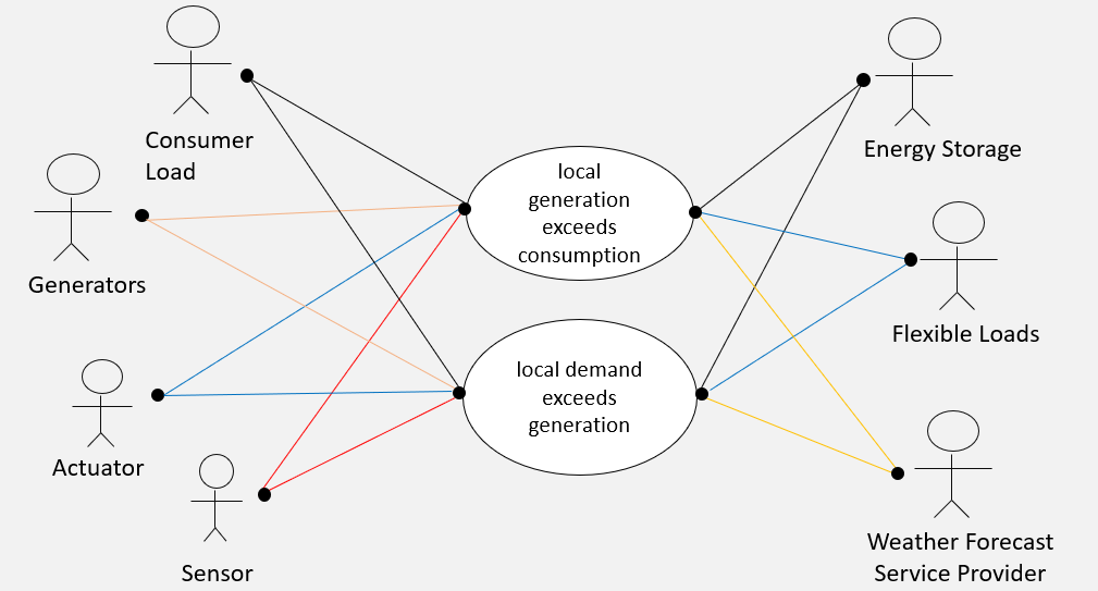
| 1 | Local generation exceeds local consumption (Islanding, when local generation > consumption) | • Generators • EMS • Consumer Load • Energy Storage • Flexible Load | Measured load flow (export) at grid connection point | • Sensors and actuators are connected with the EMS • Enough flexible loads and storages capacity are available for balancing | Demand of local flexible load and storages will be increased in order to balance generation and demand. |
| 2 | Local Ddemand exceeds local generation (Islanding, when local generation < consumption) | •Generators • EMS • Consumer Load • Energy Storage • Flexible Load | Measured Load Exchange at grid connection | • Sensors and actuators are connected with the EMS • Enough flexible loads and storages capacity are available for balancing | Demand of local flexible loads and storages will be leveraged in order to balance generation and demand. |
Notes
This part describes the possible scenarios of the use case. The scenarios should comply with the sequence diagrams in Sect. 2 of the template, so that every step describes one part of a communication or action. Apart from a normal success scenario, different failure scenarios or alternatives can be included to describe situations where preconditions are not satisfied or unwanted states are attained.
Primary Actor - the first actor appearing in the scenario at the incident causing the scenario to begin.
Triggering Event - the incident causing the scenario to begin.
Pre-Condition - indicates which terms have to be fulfilled for the scenario to be executed.
Post-Condition - indicates which terms should be valid after the scenario. TIt can also specify whether a scenario has been successfully completed or not.
4.2. Steps – Scenarios
Scenario Name: No. 1 - (Local generation exceeds local consumption)
| Step No. | Event. | Name of Process/ Activity | Description of Process/ Activity. | Service | Information Producer (Actor) | Information Receiver (Actor) | Information Exchanged |
|---|---|---|---|---|---|---|---|
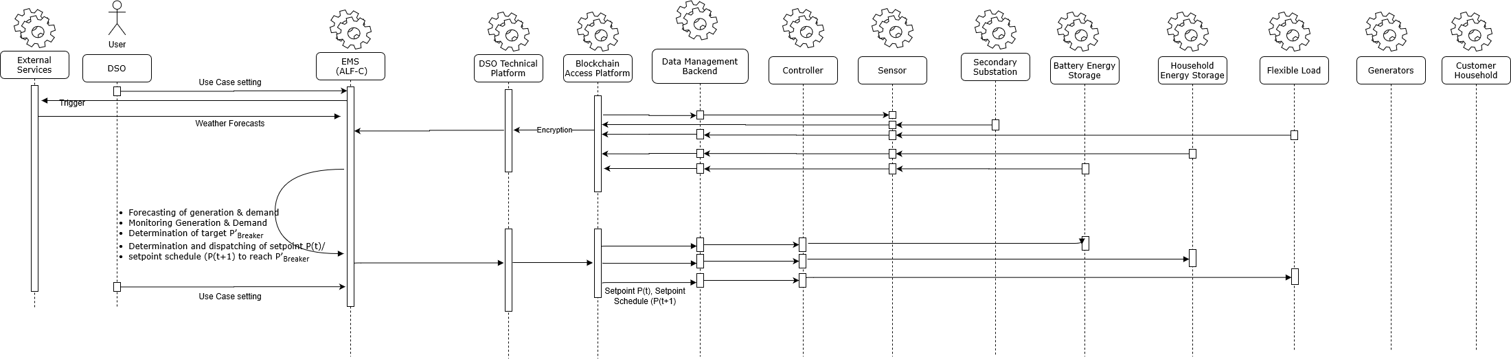
| 1 | DSO initiates UC 1 | Trigger of Use Case | Operator from Avacon sets EMS (ALF-C) mode of operation to UC 1.EMS defines the target value for load exchange along the breaker of the grid connection point to zero (P’Breaker= 0). | REPORT | DSO | EMS | I-01 |
| 2 | External service provider send weather forecasts | Transmitting the data | Service providers sends weather data and weather forecast values | GET | External System | EMS | I-02 |
| 3 | EMS receives forecasting values | Forecasting of generation and demand | An external service provider sends weather data and weather forecast values. | CREATE | EMS | EMS | |
| 4 | Sensor (grid connection point in secondary substation) provides values | Transmitting the data | The local measurement device (PMU) located at the grid connection point measures the residual power export and sends data to the EMS (PBreaker). Step will be repeated every 10 seconds. | CHANGE | Sensor | EMS | I-03 |
| 5 | Local sensors provide data via Data Management Backend. | Transmitting the data | Local sensors provide measurements values and data to the EMS.Step will be pushed every 15 minutes | CHANGE | Sensors | EMS | I-03 |
| 6 | All data collected | Evaluation and determination of control strategy and setpoints | Based on provided measurement data, asset key data. EMS calculates the power bandwith of each asset available for steering. (P_Flex) Based on generation, load and SOC forecasts the EMS calculates the optimum strategy of load and storage activation on order to maximize the duration of island mode. The EMS determines for each asset a setpoint to reach a balanced grid. The determination of setpoint is repeated every 10 seconds for BESS and every 15 minutes for flexible loads and storages located at customer premise. | CREATE | EMS | EMS | |
| 7 | Individual setpoints determined | Transmitting setpoints to controllers | The EMS sends setpoints via data Management Backend of vendors of assets to forward setpoints to controller of battery energy storage, household energy storage and flexible load located in the field to increase consumption. This signal is send each ten seconds to the BESS Management Backend and every 15 minutes to actuators located at customer premise and replaces the default signal until the EMS calculates a setpoint. | EXECUTE | EMS | Controllers | I-04 |
| 8 | Setpoint send to controllers | Verification of setpoint execution. Comparison of target and measured values | The EMS compares measured values from the grid connection point with the target values (P’Breaker = 0). In case of deviation the setpoint are redefined by walking through step numbers 3 to 10. The process is continuously cycled until the end of use case. | CREATE | Sensor | EMS | |
| 9 | End of Use Case 1 | End of Use Case 1 | The use case ends, when a DSO triggers another use case, or not enough flex is available to reach P’_Breaker. | REPORT/CREATE | DSO or EMS | EMS | I-01 |
Scenario Name: No. 2 - (Local consumption exceeds local generation)
| Step No. | Event. | Name of Process/ Activity | Description of Process/ Activity. | Service | Information Producer (Actor) | Information Receiver (Actor) | Information Exchanged |
|---|---|---|---|---|---|---|---|
| 1 | DSO initiates UC 1 | Trigger of Use Case | Operator from Avacon sets EMS mode of operation to UC 1.EMS defines the target value for load exchange along the breaker of the grid connection point to zero (P’Breaker= 0). | REPORT | DSO | EMS | I-01 |
| 2 | External service provider send weather forecasts | Transmitting the data | Service providers sends weather data and weather forecast values | GET | External System | EMS | I-02 |
| 3 | EMS receives forecasting values | Forecasting of generation and demand | An external service provider sends weather data and weather forecast values. | CREATE | EMS | EMS | |
| 4 | Sensor (grid connection point in secondary substation) provides values | Transmitting the data | The local measurement device (PMU) located at the grid connection point measures the residual power export and sends data to the EMS (P_Breaker). Step will be repeated every 10 seconds. | CHANGE | Sensor | EMS | I-03 |
| 5 | Local sensors provide data via Data Management Backend. | Transmitting the data | Local sensors provide measurements values and data to the EMS.Step will be pushed every 15 minutes | CHANGE | Sensors | EMS | I-03 |
| 6 | All data collected | Evaluation and determination of control strategy and setpoints | Based on provided measurement data, asset key data. EMS calculates the power bandwith of each asset available for steering. (P_Flex) Based on generation, load and SOC forecasts the EMS calculates the optimum strategy of load and storage activation on order to maximize the duration of island mode. The EMS determines for each asset a setpoint to reach a balanced grid. The determination of setpoint is repeated every 10 seconds for BESS and every 15 minutes for flexible loads and storages located at customer premise. | CREATE | EMS | EMS | |
| 7 | Individual setpoints determined | Transmitting setpoints to controllers | The EMS sends setpoints via data Management Backend of vendors of assets to forward setpoints to controller of battery energy storage, household energy storage and flexible load located in the field to increase consumption. This signal is send each ten seconds to the BESS Management Backend and every 15 minutes to actuators located at customer premise and replaces the default signal until the EMS calculates a setpoint. | EXECUTE | EMS | Controllers | I-04 |
| 8 | Setpoint send to controllers | Verification of setpoint execution. Comparison of target and measured values | The EMS compares measured values from the grid connection point with the target values (P’Breaker = 0). In case of deviation the setpoint are redefined by walking through step numbers 3 to 10. The process is continuously cycled until the end of use case. | CREATE | Sensor | EMS | |
| 9 | End of Use Case 1 | End of Use Case 1 | The use case ends, when DSO triggers another use case, or not enough flex is available to reach P’_Breaker. | REPORT/CREATE | DSO or EMS | EMS | I-01 |
5. Information Exchanged
| Information exchanged ID | Name of Information | Description of Information Exchanged | Protocol |
|---|---|---|---|
| I-01 | Signal from DSO via GUI | DSO triggers the use case via an GUI to the EMS to apply islanding. The trigger signal is: 0 = stop current use case 1 = application of UC 1 2 = application of UC 2 3 = application of UC 3 4 = application of UC 4 Based on the UC 1 trigger the EMS sets the target setpoint for the load - exchange along the grid connection point to zero (P’Breaker = 0). | HTTPS |
| I-02 | Weather forecasts | - Solar radiation (t + 24h) - Cloudiness (t + 24 h) - Temperature (t + 24 h) - Humidity (t + 24 h) - Windspeed (t + 24 h) | Rest API |
| I-03 | Measurement data provision | Sensors located at secondary substation, BESS and households push measurement data to EMS | PMU: MQTT or IEC61850 Household energy storage: MQTT or HTTP BESS: MODBUS/TCP or IEC VPN 608770 |
| I-04 | Sending of setpoint (t) or setpoint schedule (t+1) from EMS to BESS, household energy storages and flexible loads | Setpoint to increase or decrease demand/generation as static value [P] or relative value [%] or [SOC] | Household energy storage: MQTT or HTTP BESS: MODBUS/TCP or IEC VPN 608770 |
6. Requirements (optional)
7. Common Terms and Definitions
| Term | Definition |
|---|---|
8. Custom Information (optional)
| Key | Value | Refers to Section |
|---|---|---|