UC9
Flexibility measures II: Virtual Power Plant (VPP) services based on building solutions (IoT devices, PV and storage)
1. Description of the Use Case
1.1. Name of the Use Case
| ID | Area /Domain(s)/Zone(s) | Name of the Use Case |
|---|
| 1 | / Customer premise, Distribution / Station, Operation, Field, Process, Enterprise, | UC9 |
1.2. Version Management
| Version No. | Date | Name of author(s) | Changes | Approval status |
|---|
| v0.1 | 2020-10-01T00:00:00 | Juan Jacobo Peralta, | Preliminary description of narrative, objectives, users… | None |
1.3. Scope and Objectives of Use Case
| |
|---|
| Scope | To enhance grid operation at the distribution level by allowing flexibility mechanisms from Building Energy Management including Battery Energy Storage System (BESS), PV generation and IoT devices. |
| Objective(s) | UC09.1. Balancing energy flows to support distribution grid operation (lower operational costs, reducing grid congestion and minimizing generation curtailment). |
| UC09.2. Optimising BEM operation including control of smart devices (IoT), roof-PV generation and batteries. | |
| UC09.3. Reducing energy consumption costs and/or CO2 emissions at building level. | |
| UC09.4. Encouraging different actors (facility managers, DSOs/TSOs or energy aggregators) to request/release flexibility through the ebalance-plus platform. | |
| Related business case(s) | Associated to UC.08 (CMU role is exchanged with DERMU role) |
1.4. Narrative of Use Case
Short description
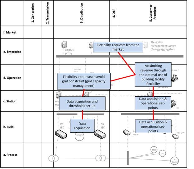
Buildings accounts for 40% of the final energy consumption in Europe and its flexibility is seen as one of the most relevant means to manage future grids and enhance their operation. This would lead to lower operational costs, grid congestion and generation curtailment, while maximising revenue through VPP services.
Complete description
| ID | Name | Description | Reference to mentioned use case objectives |
|---|
| I06a | Ratio of local production with flexible solutions (kWh produced vs consumed) (%) | Percentage of energy consumed by building facilities (smart devices) regarding energy generation/storage. This indicator can be calculated under different time ranges (hour, day, week…). | UC09.2, |
1.6. Use case conditions
| Relation to other use cases |
|---|
|
| Level of depth |
| Prioritisation |
| Mandatory |
| Generic, regional or national relation |
| Generic |
| Nature of the use cases |
| Technical & Market |
| Further keywords for classification |
| Flexibility request, congestion, peak load reduction, BEMS optimization |
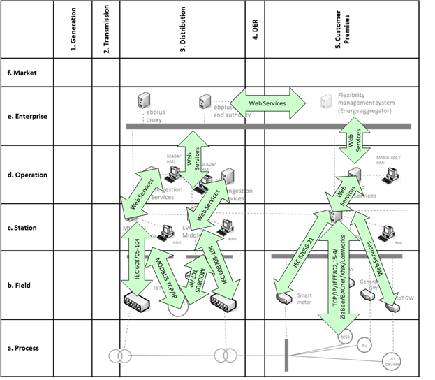
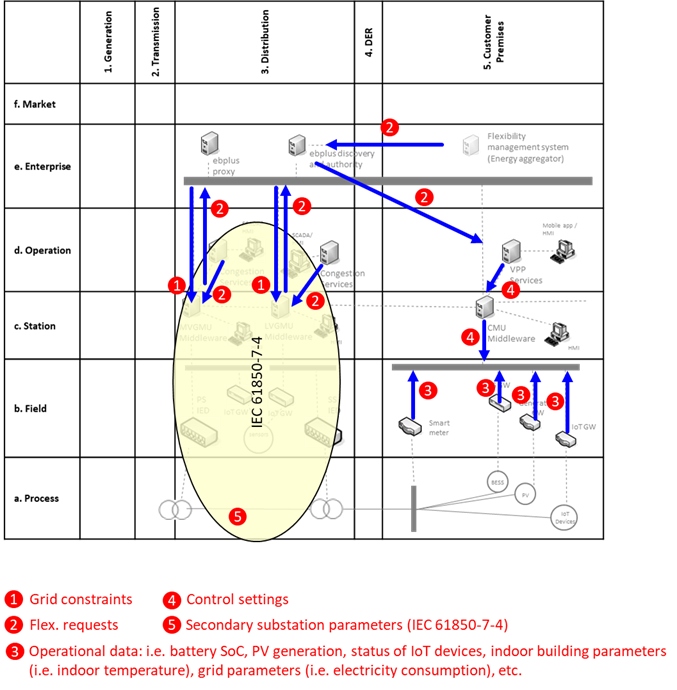
2. Diagrams of Use Case

3. Technical Details
3.1. Actors
| Actor Name | Actor Type | Actor Description | Further information specific to this Use Case |
|---|
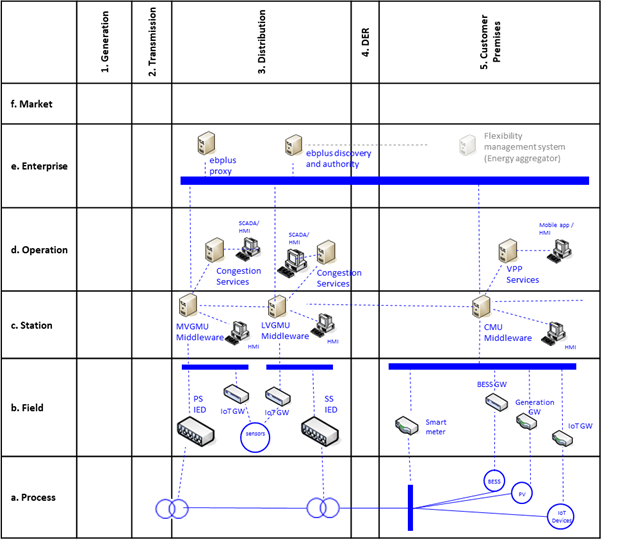
| ebalance-plus platform or TLGMU (Top Level Grid Management Unit) | System | Grid management platform to balance energy according to available flexibility | |
| ebalance-plus platform: CMU (Customer Management Unit) | System | Electronic unit that manages all the energy operations at building level, optimise energy operation and manage energy flexibility. | |
| ebalance-plus platform: LVGMU (Low Voltage Grid Management Unit) | System | Electronic unit that manages all the energy operations of management units (CMU/DERMU) connected to their secondary substation | |
| ebalance-plus platform: MVGMU (Low Voltage Grid Management Unit) | System | Electronic unit that manages all the energy operations of management units (LVGMU/DERMU) connected to their secondary substation | |
| Energy aggregator flexibility management system | System | SW that support energy aggregator to make decisions about flexibility management | |
| DSO energy management system | System | SW that support DSO to establish grid capacity thresholds in PS/SS | |
| Facility Manager | Role | A physical client of a DSO that is involved at Demo scale. | |
| BEMS | System | Building Energy Management System. | |
| Building facility component | System | All devices working on electricity that can be found in a customer’s dwelling. | |
| Customer | Role | Dwelling’s inhabitant / customer | |
3.2. References
| No. | References Type | Reference | Status | Impact on Use Case | Organistaor / Organisation | Link |
|---|
4. Step by Step Analysis of Use Case
4.1. Overview of Scenarios
| No. | Scenario Name | Scenario Description | Primary Actor | Triggering Event | Pre-Condition | Post-Condition |
|---|
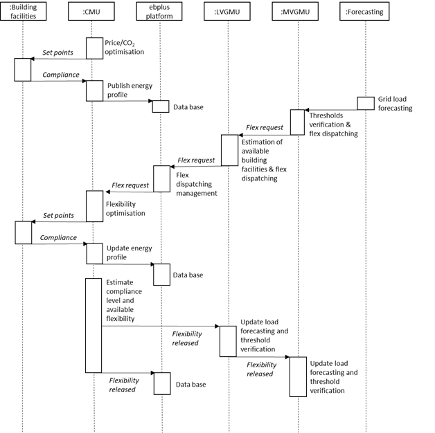
| PS1 | Grid Capacity Management using available flexibility at Customer premise domain (success) | Some grid management unit of the ebalance-plus platform (MVGMU / LVGMU) detects a forthcoming threshold overpass and calculate the necessary flexibility and request this flexibility to the corresponding CMU. | | Grid Capacity Management using available flexibility at Customer premise domain (success) | | |
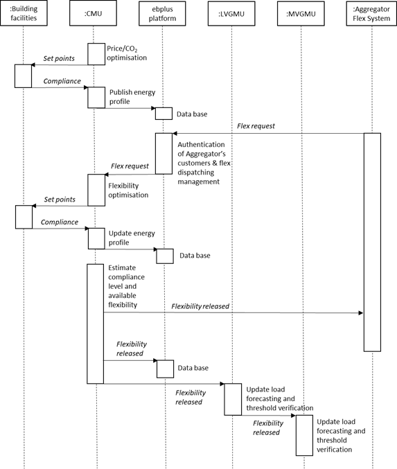
| PS2 | Aggregator flexibility management system requests flexibility | Some energy aggregator flexibility system requests to ebalance-plus platform flexibility balancing services. The ebalance-plus identifies the CMUs registered to the corresponding aggregator (authentication) and activate flexibility services. | | Aggregator flexibility management system requests flexibility | | |
| AS1 | Grid Capacity Management using available flexibility at Customer premise domain (failure) | Some grid management unit of the ebalance-plus platform (MVGMU / LVGMU) detects a forthcoming threshold overpass and calculate the necessary flexibility and request this flexibility to the corresponding CMU. | | Grid Capacity Management using available flexibility at Customer premise domain (failure) | | |
Notes
4.2. Steps – Scenarios
| Scenario Name: |
|---|
| Grid Capacity Management using available flexibility at Customer premise domain (success) |
| Step No. | Event. | Name of Process/ Activity | Description of Process/ Activity. | Service | Information Producer (Actor) | Information Receiver (Actor) | Information Exchanged | Requirements, R-ID |
|---|
| 1.1 | Periodic execution | None | The MVGMU/LVMGU located at PS/SS respectively receives power load forecasting (external/internal service) | GET | | | | |
| 1.2 | Estimation of steady state | None | Verification of DSO’s load thresholds and dispatching flexibility requests to lower units (Optimal Power Flow) | CREATE | | | | |
| 2.1 | Evaluation of flexibility request | None | The CMU optimizes the building facility energy profile to meet flexibility requests and evaluate the compliance. It generates the steering signals (set points) to the building facilities. | CREATE | | | | The structure of this data will be decided during project progress. Minimum resolution should be 15 minutes. |
| 2.2 | Compliance check | None | BEMS check & confirm flexibility level compliance (new energy profile) | CREATE | | | | The structure of this data will be decided during project progress. Minimum resolution should be 15 minutes. |
| 2.3 | Energy profile aggregation | None | CMU aggregates energy profile from building facilities and send back to the LVGMU | CREATE | | | | The structure of this data will be decided during project progress. Minimum resolution should be 15 minutes. |
| 2.4 | Energy profile aggregation | None | LVGMU aggregates energy profile from CMUs and send back to the MVGMU | CREATE | | | | The structure of this data will be decided during project progress. Minimum resolution should be 15 minutes. |
| 2.5 | Publish | None | CMU publishes energy flexibility released | CREATE | | | | The structure of this data will be decided during project progress. Minimum resolution should be 15 minutes. |
| 3.1 | Update load forecasting | None | LVGMU update load forecasting and run new steady state to verify load thresholds | REPORT | | | | |
| 3.2 | Update load forecasting | None | MVGMU update load forecasting and run new steady state to verify load thresholds | REPORT | | | | |
| 4 | Validation | None | LVGMU/MVGMU meet DSO’s thresholds and established state condition in normal operation | REPORT | | | | |
| Scenario Name: |
|---|
| Aggregator flexibility management system requests flexibility |
| Step No. | Event. | Name of Process/ Activity | Description of Process/ Activity. | Service | Information Producer (Actor) | Information Receiver (Actor) | Information Exchanged | Requirements, R-ID |
|---|
| 1 | Execution on demand | None | The external flexibility management systems request flexibility (energy profile) to their customers (facility managers). | REPORT | | | | |
| 1.2 | Dispatching flexibility to CMU | None | Dispatching flexibility requests to the CMUs linked to the energy aggregator | CREATE | | | | |
| 2.1 | Evaluation of flexibility request | None | The CMU optimizes the building facility energy profile to meet flexibility requests and evaluate the compliance. It generates the steering signals (set points) to the building facilities. | CREATE | | | | The structure of this data will be decided during project progress. Minimum resolution should be 15 minutes. |
| 2.2 | Compliance check | None | BEMS check & confirm flexibility level compliance (new energy profile) | CREATE | | | | The structure of this data will be decided during project progress. Minimum resolution should be 15 minutes. |
| 2.3 | Energy profile aggregation | None | CMU aggregates energy profile from building facilities and send back to the TLGMU | CREATE | | | | The structure of this data will be decided during project progress. Minimum resolution should be 15 minutes. |
| 3.1 | Energy profile aggregation | None | TLGMU aggregates energy profile from building facilities and send back to the Aggregator flexibility management system | CREATE | | | | The structure of this data will be decided during project progress. Minimum resolution should be 15 minutes. |
| 3.2 | Register | None | TLGMU registers energy flexibility released | CREATE | | | | |
| 4.1 | Update load forecasting | None | LVGMU update load forecasting and run new steady state to verify load thresholds | REPORT | | | | |
| 4.2 | Update load forecasting | None | MVGMU update load forecasting and run new steady state to verify load thresholds | REPORT | | | | |
| Scenario Name: |
|---|
| Grid Capacity Management using available flexibility at Customer premise domain (failure) |
| Step No. | Event. | Name of Process/ Activity | Description of Process/ Activity. | Service | Information Producer (Actor) | Information Receiver (Actor) | Information Exchanged | Requirements, R-ID |
|---|
| 1.1 | Periodic execution | None | The MVGMU/LVMGU located at PS/SS respectively receives power load forecasting (external/internal service) | GET | | | | |
| 1.2 | Estimation of steady state | None | Verification of DSO’s load thresholds and dispatching flexibility requests to lower units (Optimal Power Flow) | CREATE | | | | |
| 2.1 | Evaluation of flexibility request | None | The CMU optimizes the building facility energy profile to meet flexibility requests and evaluate the compliance. It generates the steering signals (set points) to the building facilities. | CREATE | | | | The structure of this data will be decided during project progress. Minimum resolution should be 15 minutes. |
| 2.2 | Compliance check | None | BEMS check & confirm flexibility level compliance (new energy profile) | CREATE | | | | The structure of this data will be decided during project progress. Minimum resolution should be 15 minutes. |
| 2.3 | Energy profile aggregation | None | CMU aggregates energy profile from building facilities and send back to the LVGMU | CREATE | | | | The structure of this data will be decided during project progress. Minimum resolution should be 15 minutes. |
| 2.4 | Energy profile aggregation | None | LVGMU aggregates energy profile from building facilities and send back to the MVGMU | CREATE | | | | The structure of this data will be decided during project progress. Minimum resolution should be 15 minutes. |
| 2.5 | Publish | None | CMU publishes energy flexibility released | CREATE | | | | |
| 3.1 | Update load forecasting | None | LVGMU update load forecasting and run new steady state to verify load thresholds | REPORT | | | | |
| 3.2 | Update load forecasting | None | MVGMU update load forecasting and run new steady state to verify load thresholds | REPORT | | | | |
| 4 | Validation | None | LVGMU/MVGMU cannot meet DSO’s thresholds, activates alternative strategies (see grid management use cases) | REPORT | | | | |
| Information exchanged ID | Name of Information | Description of Information Exchanged | Requirement |
|---|
6. Requirements (optional)
| Category Identifier | Name | Description | mRID |
|---|
| Req_ID | Req_Name | ‘Flexibility measures II: Virtual Power Plant (VPP) services based on building solutions (IoT devices, PV and storage)’ | |
| Identifier | Name | Description | mRID |
|---|
| VPP.EP | Energy profile | Array with energy values (positive/negative) indicating the consumption/generation status | The structure of this data will be decided during project progress. Minimum resolution should be 15 minutes. |
| VPP.FR | Flexibility requests | Array with min/max power values (positive/negative) and periods indicating the requested energy flexibility | The structure of this data will be decided during project progress (e.g., based on USEF recommendations) |
| PP.AFR | Actual flexibility released | Array with power values (positive/negative) and periods indicating the released energy flexibility | The structure of this data will be decided during project progress (e.g., based on USEF recommendations) |
7. Common Terms and Definitions
| Key | Value | Refers to Section |
|---|