UC1
Ebalance-plus Hierarchical Energy Communication Platform
1. Description of the Use Case
1.1. Name of the Use Case
| ID | Area /Domain(s)/Zone(s) | Name of the Use Case |
|---|
| 1 | / Generation, Transmission, Distribution, DER and Customer Premises / Station, Operation, Enterprise, Market, | UC1 |
1.2. Version Management
| Version No. | Date | Name of author(s) | Changes | Approval status |
|---|
| V0.9 | 2021-02-10T00:00:00 | K. Piotrowski, | Initial version of the document | None |
1.3. Scope and Objectives of Use Case
| |
|---|
| Scope | The scope of this Use Case is to describe the platform as a means to exchange data between the distributed energy management algorithms that are installed and executed on spatially distributed machines within the energy grid – management units. The scope covers the data exchange, but also other procedures needed to be done on the infrastructure management side, like registering stakeholders and their services, registering management units and defining their hierarchy. |
| Objective(s) | The objectives of the Use Case are as follows: |
| a) Platform initialization (preparation phase) | |
| o Registration of a stakeholder | |
| o Registration of a Management Unit and identification of its responsible stakeholder | |
| o Defining relations between Management Units (hierarchy relations parent-child) | |
| o Registration of a services that shall run on the behalf of a stakeholder | |
| o Defining stakeholder policies to define allowed data access | |
| b) Performing a data exchange within the platform (run-time phase) | |
| Related business case(s) | All other Use Cases exchange data based on the mechanisms described in this Use Case. |
1.4. Narrative of Use Case
Short description
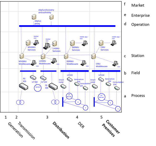
This Use Case aims at demonstrating the functionality provided by the hierarchical energy-related communication platform. It abstracts the data exchange from the main energy management algorithms and by that simplifies the implementation of distributed energy management algorithms. The Use Case presents all the steps and procedures related to the platform, needed for its proper configuration and executed during its run-time.
Complete description
The Use Case aims at demonstrating the following main steps:
a) Preparing the platform infrastructure
b) Performing data exchange between distributed processes (services) executed on distributed management units (MUs)
These two steps can be further split into procedures that need to be applied to achieve the goal of the step, but these procedures can be applied in different combinations and sequences, depending on the given deployment. But in any case the infrastructure needs to be prepared first, before the data exchange can take place.
A deployment starts with the top level units (ebplus discovery and authority). These units are responsible for the organizational procedures related to the platform, like registration, certification, revocation.
First, each stakeholder needs to be registered in the system. A stakeholder is any actor that participates in the energy grid, being either a customer or (any service) provider. A stakeholder is relevant for the platform if there is data acquired or generated by that stakeholder or related to that stakeholder. After being registered the stakeholder obtains a unique identity in the system that she can prove to others with a certificate.
In order to create the physical infrastructure for the platform it is necessary to install the management units (hardware and software) and to register each of them within the platform. Here, similar to the stakeholder registration, each management unit obtains a unique identity and a certificate to prove the identity to others. The management unit is additionally linked to a specific stakeholder that is in charge of the management unit and has physical access to it. This stakeholder and management unit relation can be, for instance, defined by the premises the unit is installed within. After a management unit is registered in the system, it can be attached to the existing topology of units by defining its place in the hierarchy within the platform. This definition is done by creating a parent-child link between two management units. This relation is 1 to n, meaning that one parent can have many children, but one child can have only one parent (at a time). To define this link, it is necessary to configure both the management units properly, i.e., the child is added to the children configuration set on the parent MU and the parent is added to the parent (one element) configuration set on the child MU. This setting is local to this two MUs, it is not forced or configured by the top units, as it can be dynamic if the deployment allows topology/hierarchy changes, for instance, to improve the reliability.
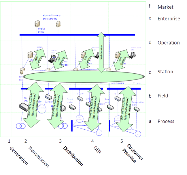
In order to create data sources and exchange points it is necessary to register services that use the platform. A service is an implementation that accesses the data in the platform and executes a local algorithm processing the data and triggering actions or generating new data. These local services cooperate and together they implement a distributed algorithm. The locally installed piece of software (service) is executed on a management unit on behalf of a given stakeholder. It means that the same piece of software may be executed on the same management unit but for different stakeholders. By that we have two different instances of the algorithm, but performing their tasks for different stakeholders. Thus, within the platform not the piece of software – service is registered, but its specific instance to be run by a specific stakeholder. Such registered services to be run by specific stakeholders also get their certificates to prove their identity. This approach allows to specify data access policy that allows restricting the data accesses for specific algorithms by specific stakeholders only.
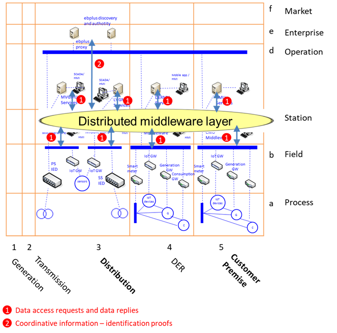
Data stored by a service onto the platform is labeled as data belonging to the stakeholder the service runs on behalf of. By default each service run for a given stakeholder can access the data by that stakeholder without restrictions. But in order to access data of other stakeholders it is necessary that a proper access control policy is defined. Such policy specifies the allowed access patterns for given stakeholder/service configurations. And as the data access policy is handled by the MU where the data was written by a service of a stakeholder, it is also necessary to define the policy at that management unit. The best way to do that is to set it up while the service first starts. The access policy is then available on other MUs in the platform as well.
Finally, the data exchange between the running services may happen. The data exchange ways include reading, writing data, but reading can also be extended to subscribing to specific events, resulting in periodic data delivery or delivery of each newly available value. To exploit the hierarchical feature of the energy grid it is advised to perform data exchange according to the parent-children hierarchy, but indeed any other data exchange is possible as well. It is only necessary to know the identity of the target management unit, where the desired data origins from. Additionally, it is of course also necessary to have the right to access the desired data (policy definition by the data owner).
| ID | Name | Description | Reference to mentioned use case objectives |
|---|
| KPI.1.01 | Platform reliability | Each data exchange request shall be accomplished with a clear outcome. Each condition in the platform has a defined influence on the data exchange result. Analysis of the platform state under the existence of data exchange requests gives a metric of the system reliability. | Objective b), |
1.6. Use case conditions
| Relation to other use cases |
|---|
|
| Level of depth |
| Prioritisation |
| Obligatory |
| Generic, regional or national relation |
| Generic |
| Nature of the use cases |
| Technical |
| Further keywords for classification |
| Information Management System |
2. Diagrams of Use Case
3. Technical Details
3.1. Actors
| Actor Name | Actor Type | Actor Description | Further information specific to this Use Case |
|---|
| Data source | Any service by any stakeholder | Any service by any stakeholder storing data in the platform | |
| Data sink | Any service by any stakeholder | Any service by any stakeholder reading data in the platform | |
3.2. References
| No. | References Type | Reference | Status | Impact on Use Case | Organistaor / Organisation | Link |
|---|
4. Step by Step Analysis of Use Case
4.1. Overview of Scenarios
| No. | Scenario Name | Scenario Description | Primary Actor | Triggering Event | Pre-Condition | Post-Condition |
|---|
| PS1 | Storing data | Data source stores data in the platform | | Storing data | | |
| PS2 | Reading data | Data sink requests and obtains the data from the platform | | Reading data | | |
Notes
4.2. Steps – Scenarios
| Scenario Name: |
|---|
| Storing data |
| Step No. | Event. | Name of Process/ Activity | Description of Process/ Activity. | Service | Information Producer (Actor) | Information Receiver (Actor) | Information Exchanged | Requirements, R-ID |
|---|
| 1.1 | Data source issues a store request | None | Data source issues a store request. The data source is identified by the platform. | None | | | | |
| 1.2 | Platform stores the data and replies with a reply. | None | After successful processing of the request the data is stored in the platform. | None | | | | |
| Scenario Name: |
|---|
| Reading data |
| Step No. | Event. | Name of Process/ Activity | Description of Process/ Activity. | Service | Information Producer (Actor) | Information Receiver (Actor) | Information Exchanged | Requirements, R-ID |
|---|
| 2.1 | Data sink issues a data read request | None | The data sink issues a request to read the data. The request may be either a single reading or a subscription for a series. The platform identifies the data sink and verifies if the data sink can access the requested data. | None | Data sink | | | |
| 2.2 | Platform issues a reply for the request | None | After successful processing of the request the platform replies with data. This can be a single reply or a series of reply messages. | None | | Data sink | | |
| Information exchanged ID | Name of Information | Description of Information Exchanged | Requirement |
|---|
6. Requirements (optional)
| Category Identifier | Name | Description | mRID |
|---|
| Req_ID | Req_Name | ‘Ebalance-plus Hierarchical Energy Communication Platform’ | |
| Identifier | Name | Description | mRID |
|---|
| EB.WR | Store request | Store request, containing the data to be stored together with meta description of the data and the identity of the data source (the requester). | EB.WR |
| EB.WRR | Store reply | Store reply, containing the result of the request processing. | EB.WRR |
| EB.RD | Read request | Read request, containing the meta description of the requested data and the identity of the data sink (the requester). | EB.RD |
| EB.RDR | Read reply | Read reply, containing the result of the request processing and the requested data (if the access was granted) | EB.RDR |
7. Common Terms and Definitions
| Key | Value | Refers to Section |
|---|